Sunday, September 4, 2016

Pi Based Physical Access Control


So I've been working with a friend on a pi-based access control system as a proof of concept.  I took a lot of things I've learned so far, like building a relay board and other general low voltage shenanigans.  We've been winging it but everything seems to be coming out quite nicely.  Our prototype is essentially done but just needs to be tied into some type of authentication back end.  Also it currently uses a barcode scanner (not pictured) but I would imagine you could integrate any identity collection device that uses serial.

So what does it do?

1.  Outputs whether or not it's ready (via optional outputs for status lights)
2.  When ready, listen to serial input for a barcode (or other credential)
3.  Check credential against an access file, database, etc.
4.  If approved, trigger a relay to grant physical access for a few seconds otherwise do nothing.
5.  Plus possibly more features to be implemented as we refine things.

I feel like it's a bit easier to explain going in reverse from the input/output of the system down to the pi and code.

Power

Power comes in via a 12v barrel jack connector and onto a supply block.  Power goes from there to the main access control interface which has 5 connectors:
+12v supply
-12v supply
Relay in
Relay out (Normally closed)
Relay out (Normally open)

The relay I'm talking about is that black box on the bottom left, it's a 12v 30A automotive relay.  Right now power goes into it and the normally opened output goes to a normally locked magnetic strike plate.  When access is granted that plate is unlocked.  You could also use the normally closed connector to power a magnetic door lock that would release when access is granted.

12v/5v supply

12v comes from the supply block and goes to the blue screw terminals on this legit regulator but also continues off to power the 12v rail (right side of the breadboard).  It outputs to a +5v and -5v solder points (next to the usb connector) where we added wires to power our 5v rail (left side of the breadboard).  It also outputs USB that powers the pi.  We might drop the USB cable and run jumper wires from the 5v rail on the breadboard to the +5 and ground pins on the pi to power it (which works but they are not soft-fused inputs like the micro usb port).  This is a DROK regulator and it's awesome, it can accept from something like 4-40 volts and outputs 5.  There is a trace that you have to cut on the PCB if you want the USB port powered when the regulator starts up, otherwise you have to push a little button on the regulator to enable power to the USB output...every time.

The first stage relays

To drive that big 12v automotive relay, we're using some small relays with a 5v coil.  If you look closely there are two identically setup relay circuits on that breadboard.  The one on the right is the system ready/busy relay.  The one on the left is the locked/unlocked relay.

Each relay has 5v going into the coil, and the other end of the relay coil connects to the collector pin of a transistor.  The emitter pin goes to ground.  An LED also is powered by the 5v rail and grounds through the collector on the emitter.  A wire from GPIO feeds through a 330 ohm resister (so you don't pull more than 16ma from the pi's GPIO) into the Base pin of the transistor.  Each relay has a blue LED that comes on when powered.  I did measure the draw in mA from the pi which is about 6-7 and well below the 16 or so that can damage it.

Although this pair of yellow relays are DPDT (dual pole dual terminal) we're only using one side of it.  Notice the black wire going from the +12v rail on the bottom into the input of the relay, and both  output poles go to separate block terminals (and there is one common ground).  So then there is a red momentary button, followed by four LEDs, Red, Green, Red, Green.

The left red/green LEDs tell you if the system is granting access.
The right red/green LEDs tell you if the system is ready.

Notice that the 1st and 3rd terminal on that block have some extra crap going to them.  First, there are a set of wires for GND and +12v that power the coil of the big relay.  Secondly, a diode hooked up in reverse polarity to protect against transient voltage output from the big relay's coil when you stop powering it.  Apparently when you stop powering a relay coil, it's magnetic field collapses and it can generate and output some power and it is helpful to have a diode or relay to suck some of that transient voltage up and protect your circuit.  This is why I put a diode on all three relays and one on the strike plate (which shipped with it).  Anyways Google/Wikipedia are here to help!
It is important that you use GPIO pins that are OFF, or "Low" by default (boot state) otherwise your system could say it's ready or grant access before it should.  We used GPIO pins 17 and 27.

System is ready, but being manually triggered.

So pushing the red button grounds the access relay and bypasses the transistor hooked to GPIO.  This will in turn trigger the bigger relay.  This is different than a "push to exit" button which you'd probably have interrupt power to the lock with a normally closed momentary switch.

The strike plate

This strike plate unlocks when powered, which happens when the big relay is triggered, which is triggered when the smaller access relay is triggered, which is triggered via GPIO from the pi.

The serial interface


The barcode scanner that we were using (not pictured) is a USB handheld type with a pistol grip.  The interface was USB to a modified RJ45 with an extra pin on either side but they are unused.  We were able to figure out the pinout and hook an RJ45 jack (bottom left) that allows us to use a regular Ethernet cable straight to our scanner.  We had to scan config barcodes that put the device into serial mode and disable the carriage return.  Anyways pin 1 goes to the +5v rail, pin 2 to the -5v rail, pin 7 to ground on the pi, and pin 8 to the serial GPIO pin which is GPIO 15 (RXD UART).  I believe this differed significantly from the regular serial to RJ45 pinout.  I don't remember exactly where it was, but in the latest Raspian build the serial UART is disabled by default.

The code

We wrote everything in python, and aside from reading serial being a bit of a pain, we were able to put everything together with just a few simple functions.  The nice thing is that by nature this app needs to be single threaded because it does everything in a sequence.  The pi runs a loop that listens on the serial GPIO/UART/RXD pin for a credential to be scanned which is sent as a string, checks if it has access (a basic if statement right now), then calls a function that triggers the relay (if the person is authorized).  There is a function to set the state, where you pass it "ready" or "busy" and it sets the "state" relay accordingly that lights up green when ready or red when busy.  The beginning of the loop sets the state to ready, and as soon as it gets data from the scanner it sets state to busy until it's checked the person and granted access (if applicable).


The main loop.  It runs indefinitely and should never stop, unless there is an exception, which if detected will clean up the GPIO outputs.


Setting up serial.  Serial is kind of a pain in the ass to get working but extremely powerful.  As I mentioned before there was a bug with raspeian where UART RXD Serial was disabled by default.  I think until we found to enable it we weren't able to find /dev/ttyS0.


Setting up the GPIO outputs.  17 outputs the ready state, 27 triggers the access relay.  Notice the "initial=0" arguement which is optional, it makes them not set high as soon as you set them up.


Function that gets passed "ready" or "busy" and sets the status relay accordingly  There may or may not be status lights connected to this relay as it is for optional outputs.


Function that keeps reading from serial until it gets something other than an empty string, then returns it.


Function that when passed a credential, returns a 1 or 0 based on if it recommends access or not.  In this example it is a dummy function that sleeps for a second to simulate a backend lookup.  If you scan a can of vanilla coke zero it will grant you access, as the test value is the UPC code of said can.


Function that gets called when access is granted.  It's passed a number of seconds as an arguement and will grant access (power GPIO27, which triggers the transistor, which triggers the small access relay which triggers the large access relay) for the passed number of seconds.

Operation

So the script is a service and runs as the pi starts.  So basically you power the whole board and in about 9 seconds the pi boots and the state changes to "ready" when the script starts and sets the ready state.   You scan a barcode and the state immediately changes to "busy".  It looks to see if you have access, and if so triggers the door, and goes back to "ready".  If you don't have access, it just goes back to "ready" without granting access.  Basically if you are holding a can of vanilla coke zero you have access (as that's the UPC we granted).  If you are holding a jug of tide or something else, you don't have access.  We put a time.wait in our lookup function to simulate a database lookup or back end call to an authentication server.

Thursday, August 25, 2016

Raspberry Pi GPIO Part 2: Relays

The relays arrived.  They are neat.


These are uxcell HK19F relays, which came in a pack of 10x for $6.89 and free shipping from Amazon.  Just make sure you pick a seller that is in your local country unless you want to wait a month because there are so many Chinese sellers on amazon now.  They're DPDT which means Dual Pole Dual Terminal, so there are two individually switched inputs that each go to two different outputs.  One is normally open, and one is normally closed.  If you saw my previous blog post about the hotwheels radar gun, I need this to simulate the trigger which bridges one pair of wires when the trigger is pulled and bridges the other pair (to show top speed) when the trigger is released.


Here I will give you poorly constructed explanation of what I perceive to be going on.  I've also traced the diagram since it's really hard to see.
When the coil is not engergized Input 1 is bridged to Output 1A and Input 2 is bridged to Output 2A
When the coil is energized Input 1 is bridged to Output 1B and Input 2 is bridged to output 2B
It's possible that I have normally open/normally closed swapped because I did not verify, but am assuming that the image shows the relay in the "unpowered" state.

Increasing the 3.3v GPIO output to run a 5V relay coil

So unfortunately the output of the GPIO pins is 3.3v and very low current, so we're going to need to amplify it somehow.  We're going to use a transistor to do this.  You've probably heard about how transistors revolutionized technology and made computers smaller than buildings and radios smaller than refrigerators by replacing vacuum tubes.  Me too, but I had no idea how they worked.

This is a transistor.  It's main function is to act like a switch that's toggled by a very low amount of power (sort of like how a relay works).  However a transistor and be activated by a lower amount of power than a relay, but cannot handle as much current as a relay.  In some cases you can use a MOSFET which is sort of like a beefy transistor with a heatsink which can kind of do both jobs reasonably well.

The Emitter pin (bottom) goes to ground.
The Collector pin (top) is what your circuit should ground into.
The Base pin (middle) is what you give a tiny bit of power to and it opens the flow from Collector to Emitter.  Think of a transistor as a valve and by applying power to the Base pin you're opening the flow of electrons from Collector to Emitter.

These rules Assume you are using an NPN transistor.  A PNP transistor is totally different, it does something like positive power supply to Collector, Emitter to your circuit, and power can flow when base is grounded.

Ok, so +5V supply red wire, goes to one side of the coil on the relay.  The other contact on the relay coil goes to the collector pin on the transistor.  The emitter pin on the transistor goes to ground via the black wire.  The grey wire is a 3.3v GPIO output from the pi going to the base pin on the transistor.  Use a resistor where gpio enters the transistor, not shown.  You dont want to pull more than 16mA from the pi or you can damage it. 330 ohm worked for me and dropped draw from 40mA to 7mA When a small 3.3v current is applied to the base pin, the transistor allows the 5 volts to pass through the coil on the relay which toggles which outputs are connected to the inputs.

Here's a closer look:

The Brown wire is going from a 3.3v output (rail, not GPIO) on the pi to input2 I talked about above (remember the relay is flipped over now so input2 is on the left now).  I have output2B going to the positive lead of an LED, and the other lead going to ground.  The LED is on the normally open output but the reason it's lit up is because the program is already running in this picture.  I ran a simple python script that toggles the GPIO output on and off every second (which I covered in the GPIO part 1 post).  If I connected a second LED to output2A then the LEDs would alternate as the relay is cycled and would never be on at the same time.  There's just really one thing that's missing here...


This is a diode.  A diode only lets power flow one way.  Apparently when driving a relay with a transistor you're supposed to put a diode across the coil IN REVERSE.  Basically the positive lead on the diode needs to go to the negative side of the relay coil and the negative lead on the diode needs to go to the positive side of the relay coil.  The reason for this is that you are creating a magnetic field in the coil to open it, and when you stop powering the field that coil can output power as the magnetic field collapses and damage your transistor (sort of like how a motor spins when you power it but then outputs some power when spun).  Allegedly this is the reason why, and I might not even be getting that right, so you might want to look up the reason yourself.  Anyways I recommend you put a diode in backwards because every example I've seen says to.  It will be obvious if you have it "wrong" (not backwards, and yes this is super counter-intuitive) because your relay will never cycle and your transistor might burn out (as there is no resistance in the diode so it just lets you bypass the coil and dump all that power from the +5v rail to the ground straight through your diode (which will get hot from that much current) when you introduce a current on the gate pin).

So there you go.  Relays are kind of fun because you can hear them cycle as they're mechanical.  As my relay turned on and off it sounded like the turn signal of a car (which coincidentally operate off of... relays!).

So we're taking about 15mA at 3.3v from GPIO and using a transistor to enable a 5 volt circuit.
That 5 volt circuit opens and closes circuits on the relay.
That relay can handle 1 Amp at 125VAC or 2 Amps at 30VDC.

Go big or go home

Now I don't believe there is a reason you can't "stack" relays, and this is probably actually a thing and there is probably actually a name for it.  So in theory you could use this not very big relay to toggle a 12v circuit that powers the coil of a huge ass relay, effectively toggling hundreds of amps with your wee little GPIO output.

Sunday, August 21, 2016

Raspberry Pi GPIO functional examples (Read/Write)

"The knowledge, it fills me. It is neat."
          -Gir, Invader Zim

One of the things I've been putting learning is how to read voltage on GPIO pins, as well as output a voltage to turn devices on.  Using an LED that can handle up to 3.5 volts or so, and a motion sensor module that outputs a 3.3v signal, I figured out the basics.  There are three things I'm going to go over, and those are sensing voltage, outputting voltage, and sensing continuity using GPIO pins.

For most of this section I'm using HC-SR501 motion sensors from Amazon (Most are sold from China but A seller named "Nevada Robotics" ships them prime).

This sensor is great because you can power it with 5 volts (what the pi outputs) and it in turn outputs a signal of 3.3 volts (what the ideal/max voltage is to sense with GPIO is).  When it outputs a 3.3v signal, it really just outputs a voltage of 3.3v at a low current.  If you want to run a 3.3v device off of it you will need to use a transistor, and even a relay if it's a higher draw device.  Your motion sensor and pi need to be grounded together if they are not running of of the same power source.  These motion sensors have two screws on the back, one that will control how long the output signal lasts on motion (which I turned all the way down), and another that will control how sensitive the device is (which I turned all the way up).  I forget which is which but the data sheet is easy to find with some moderate google-fu.  Also keep in mind that the documentation on this sensor said it's somewhat unreliable for the first 60 seconds while it starts up, but it seemed fine to me!

Also you can refer to the GPIO pinout on this page so that you know what pins I'm using.

Sensing a signal (voltage)

Here's a little breadboard.
Top red/black pair: Power to the breadboard
Bottom red/black pair: powering the motion sensor
Brown: signal from motion sensor
Yellow: to pi's GPIO 4 pin
LED: Also lights up when motion is sensed to help with debugging

Here is some code that you can run.  You define GPIOPIN=4 so that it knows you are working with GPIO4.  Since we are using GPIO.setmode(GPIO.BCM) it's going by the pin numbers on the Broadcom chip channels, or something.  The other option is something like GPIO.BOARD if you wanted to reference the pins by placement number.  I went with GPIO.BCM since you have to look at the diagram to see which pins can do GPIO anyways.

So DetectMotion() will return a 1 or 0 when called; 1 means there is currently motion and 0 means there is not.  Motion meaning it's sensing 3.3v on the GPIO4 pin, because I'm using a motion sensor.  You could have this sense anything that outputs 3.3v, or a higher voltage if you use appropriate resistors.

Then we have a infinite while loop that is constantly calling DetectMotion and if it ever comes back with a 1, prints out "Motion was detected!".  It will only do this once no matter how long the motion/signal lasts for because it's got a while loop that just passes (does nothing) until there is no motion/signal and it exits the loop.

The whole thing is wrapped in a "try" so that when it gets an exception (KeyboardInterrupt) it can run GPIO.cleanup() which removes the configurations from your GPIO pins so you don't get nasty errors that they are in use the next time you run the script.

And this is what you should see!  Every time the LED lights up it should say "Motion was detected!".

Outputting a signal (voltage)

Here is an even simpler breadboard.  Grey is going from GPIO27 on the pi to the positive lead on an LED which has the other lead grounded.  Again your LED usually needs to somehow be grounded to the pi but in this case I'm using the same 5v power source so it does not.  Also use a resistor to limit draw from GPIO to 16mA or less.

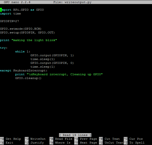
Here's an example of some code that will make the LED blink by alternating 3.3v and 0v out each second on GPIO pin 27.

Of  course the output in the console is very anti-climactic.  I should have put in an echo that said "turning light on" when setting the pin to 1 and "turning light off" when setting the pin to 0.  Now your output doesn't necessarily need to go to an LED, it can go to a transistor to drive a relay.  I'm still learning about transistors myself but have ordered some releays that will get here in a few days.  When they do, I'll write something up on how to drive them via a pi.

Having an input signal trigger an output signal

You're then able to use an input signal to trigger an event in python code that will turn on or off your output signal.  So lets make it so that when our motion sensor sends the pi a 3.3v signal, it will blink the LED quickly.  We'll set up the breadboard as so:


The lower Positive/Negative pair are powering the motion sensor.
The brown wire is the signal coming from the motion sensor.
The yellow wire is going to the PI's GPIO4 pin.
The grey/purple wire is coming from the PI's GPIO27 pin to the positive end of a grounded LED.


Here is some code that listens for a signal on GPIO4 and will output one on GPIO27.  Notice that I had to pick new names for the pins since there are more than one.  Instead of GPIOPIN, I'm using GPIOinput and GPIOoutput.  You will need to also update any references from GPIOPIN in your code if applicable.  You only need to do GPIO.setmode(GPIO.BCM) one time for any GPIO pins you reference.

You can see how the GPIOinput and GPIOoutput pins are setup on seperate lines, then I toggle the output to 1 for 1 second, then toggle it to 0.  I did this for two reasons, first when you set up the the output it seems to start as 1 so you need to disable it, and secondly having the light come on for 1 second helps you know that the script is actually starting properly.

The definitions (functions) should look really familiar from the examples above.  The whole thing runs forever in that while 1 loop, where whenever motion is sensed, the pi will keep calling the "ToggleOutput()" function until it stops.  The "ToggleOutput()" function blinks the LED and this time actually prints "blink" every time the LED is going to blink.  With a .1 second sleep, you should see the light flash about 5 times a second (but only when there is motion.


And there you have it!  When the sensor sees motion, it sends the 3.3v signal to the pi.  that triggers the pi to tell you that there was motion and start repeatedly calling the ToggleOutput() function that blinks the LED as long as the motion continues.  At the end of the runtime there was a longer set of blinks because it was longer continuous motion.  Neat!

Sensing continuity

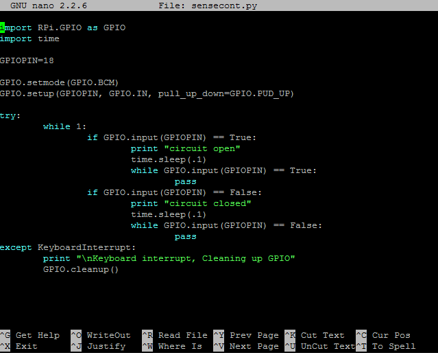
Sensing continuity is fairly straight forward.  You basically create a signal on a GPIO pin and sense when it drops (from being grounded).  So what I did is use GPIO18 and a GROUND pin to go to a switch.  When the circuit is open, the input will show True.  When the circuit is closed, the input will show False.  The difference in this from sensing an input is that we are using PUD_UP to supply a small voltage to the pin we are listening to which will make the pin show False until it is grounded.

Now just connect wires to GPIO18 and GND.  Then connect those wires to a switch, or just strip them and you can touch them together to simulate a switch.  The reason for the .1 second sleep is that I saw a little bit of jitter on state changes.  That's probably because I was just doing a bad job at making a solid contact.

Here's what you will see as you touch the wires together and pull them apart (or toggle a switch if you are using one).  I'm using this to sense my garage door through a magnetic reed switch, and my script will text me with a timestamp whenever the door becomes open or closed.  The while/pass portion makes it so that you only have your event happen once time on each state change.  I had the option to use a normally open or normally closed switch.  Well I used a normally closed switch for my garage door, so if the wiring ever fails it will tell me the door is open and I'll be forced to go check "why my garage door opened at 3am" (sort of a failsafe).  If you use a normally open switch, and your wiring fails, it will just never alert you when your door opens.

Well hopefully this helps!  It's been a lot of fun learning this and you can imagine all the projects that this opens your pi up to.

Thursday, August 18, 2016

Adventures in Radar with the Raspberry Pi (Part 2)

This is a continuation on a previous post, which you are advised to read first.

"It came!  It finally came!" -Sid from Toy Story.  Also myself.

Alright, lets rip this shit open!

Well this is embarrassing... I did not mean literally!  I had a lot of trouble with drilling out the screw caps, which was compounded by the fact that the cheap plastic was also very brittle and kept "grabbing" the bits.  I could have done this really cleanly with a drill press but since I was drilling freehand the bits kept pulling and stripping screws.  Since the whole process was going to disastrously anyways, I ended up just tearing it apart.


Pay no attention to the huge dent in my waveguide from the drill bit!  Hopefully it won't affect anything too much...

So we have the RF TX/RX module with a waveguide soldered to it.  Then there is a little PCB with the screen and buttons on it.  Finally there is the end of the battery holder with a dual pole dual terminal switch for the trigger.


Here's a picture of the back of that battery holder/switch assembly.  There are two sets of wires, Brown and Blue.  It looks like when you pull the trigger, the blue wires are bridged to take a reading, and when you let go, the brown wires are bridged to report the highest captured value.  I've already ripped off the black and red positive and negative terminals from the battery connector.


Here's a closeup of the board and the radio module.  There are only three wires going to the radio module, red, black and white.  Black is ground, white is "SIG" (our Doppler shift signal), and red is "VOSC" which I can only venture to guess is "voltage oscillated".  This is important because I vaguely remember that some devices are "pulsed" as opposed to a continuous wave.  I'd be worried that taking out this board would then change the way the radar module operates.


I powered up the device with some alligator clips and waved by hand in front of the waveguide and it registered 512 miles per hour.  That did not seem right.  Then I remembered that red switch on the left controls "Scale", so that you can radar a hotwheels car and figure out how fast it would be going if it were the size of a real car (it just turns on a 64x multiplier for speed).


This seems more reasonable.  Obviously you have to push and hold the button (simulating a trigger pull) to get real-time readings, and highest speed is reported when you let go.


Alright, time to solder some breadboard leads onto the wires that used to go to batteries.  If you solder but don't have a set of "Helping hands", get one.


Seeing as how everything seems to work, I then soldered a breadboard wire onto the SIG connection to try to tap into the signal coming out of the radar module.  This picture courtesy of the magnifying glass on my "helping hands" that I was repping above.  Unfortunately the GPIO input of the PI did not register anything.  I hooked up a volt meter which will only give a rough idea because I'm checking the voltage of sine wave (I guess) and only picked up about .04 volts.  Bummer, I'll need to figure out how to get that up to something reasonable to get the pi to read it.  Feeling defeated I gave up for the day.

BRO OF THE WEEK AWARD

goes to "Zerodegreec" for his contribution in reply #7 of this post on the arduino forums seen here:
This is super exciting because this "test point" he's referring to leads to the signal from the radar unit AFTER it's been amplified.  I took a reading on it and it seems to output over a volt which is 20x more power than I was seeing from the SIG wire out of the radar module.  I don't know if there is a way to directly convert the reading of a voltage of a frequency, but "more" is good enough for me to get my hopes up!  Also notice in this picture that a brown wire was added to go to the ground of the ATmega644 that was connected to the test point; I did not need to do this because the pi and radar module are being powered by the same 5v power source (the USB battery) with a common ground.


I soldered a breadboard wire to the "test point" on my board.  It's on there but barely.

There, much better!  The hot glue that came on this thing is obnoxiously effective so I added some of my own.

Since 5v into the pi's GPIO will release the magic smoke (I'm feeding this board 5v), I tried first with a 1k resister, the same size that I was using to drop the 5v signal to about 3.3v on the old radar module.  I connected the the lead on the other end of my resister to the pi, pulled the trigger, waved my hand in front of it and hoped for the best!


Neat!  Except for that last reading which must be an anomaly.


This is a capture of me walking towards the module.  According to wikipedia, the average human walks at 3.1 mph.  The average human however isn't usually carrying a laptop and walking like an idiot while being overly conscious about trying to walk a normal speed.  What I noticed is that when nothing is really moving there are virtually no readings, and this is awesome.  The previous radar module I tested had tons of background chatter, so much so that I told my script to only output readings over 3 mph.  Lets try something a little faster...


I figured a flap made of foil tape on a bike tire rotating in the path of the RF would give me some kind of reading.  With the bike upside down I turned the pedal for a bit and pulled/released the trigger button so I could compare the top speed the radar captured with the top speed my script captured:


Seems pretty close to me!  The samples are really poor as it's a small target but the LCD reported 25 and my pi reported 27.07.  I'm wondering if the fractions of miles per hour are the Doppler shift of the wheel vibrating or something.  It's time to find something with a little more consistency.


I pointed the waveguide at the fan in different angles until I found one that the value didn't fluxuate much at all.  Some angles I was getting up to 40mph (with very poor consistency) which makes sense because the amount of Doppler shift is going to be affected by your angle of reading due to the cosine effect.  I started getting a really solid reading that was showing 12 miles per hour on the LCD screen.


Look at that!  Those are some solid readings!  I tried a few different tweaks and it seems like the best results were sampling the signal and waiting for it to decrease in voltage twice, and finding the time between them.  Then I averaged three such readings to get a more consistent speed.  I might not even need to calibrate as this radar module is 10.525Ghz just like the last one, and thus the same equation of 31.36Hz per MPH still seems to apply.  I'll probably still need something to remove the occasional anomaly though I only saw that when I had my hand within a few inches.


My current code.  When you call the "getspeed()" function, this is what happens in a nutshell:
1.  Wait for the GPIO voltage to be falling (signal wave dropping)
2.  Set the variable "start" to the current time
3.  Watch for the wave to drop two more times
4.  Subtract the start time from the current time to get the "duration"
5.  Divide the number of cycles (samples) by the "duration" to get the frequency in Hz (or waves/sec)
6.  Divide the frequency (in hertz) by 31.36 to get "speed" (miles per hour)
7.  Return said speed

So in the while loop I'm just adding the result of the getspeed() function three times and dividing by three to get an average.  I also have another IF statement below to take a picture if a certain speed is exceeded (not pictured).

What's next?
Now I need to put everything else together.  My plan is to get a DPDT (dual pole dual terminal) relay for the trigger assembly.  This will basically give me a relay that when I power the coil, it will take a radar reading, then when I stop powering the coil it will revert to the "highest" state (remember the trigger has two pairs of wires going to it).  That will allow me to have the LCD screen output the highest captured value after a sample, so that I can compare it to the highest value returned by the pi to see if they match.

How will I toggle the relay?  I've been experimenting with some HC-SR501 Passive Infrared Motion Sensors.  They have a 3.3v output that I should be able to run straight into GPIO and sense when they are triggered.  here is one that I was using to light up an LED when there is motion:


So my idea is that the pi will be alerted to motion when the PIR is triggered and sends a 3.3v signal to the pi via GPIO.  Then the script, having sensed the motion, will start listening for signals from the radar module while simultaneously outputting 3.3v to a different GPIO pin going to a mosfet that will turn on the power to the radar module.  After capturing a few seconds of signal from the radar module the pi will use the highest one using the "max()" function, and I can compare that against what the LCD shows as the highest value captured.  The range of the PIR is only about 7 meters so I might want to have the radar measure targets as they leave AFTER the PIR motion sensor detects them passing by.

Well that's all for now!  Hopefully you are smarter now!