-Gir, Invader Zim
One of the things I've been putting learning is how to read voltage on GPIO pins, as well as output a voltage to turn devices on. Using an LED that can handle up to 3.5 volts or so, and a motion sensor module that outputs a 3.3v signal, I figured out the basics. There are three things I'm going to go over, and those are sensing voltage, outputting voltage, and sensing continuity using GPIO pins.
For most of this section I'm using HC-SR501 motion sensors from Amazon (Most are sold from China but A seller named "Nevada Robotics" ships them prime).

This sensor is great because you can power it with 5 volts (what the pi outputs) and it in turn outputs a signal of 3.3 volts (what the ideal/max voltage is to sense with GPIO is). When it outputs a 3.3v signal, it really just outputs a voltage of 3.3v at a low current. If you want to run a 3.3v device off of it you will need to use a transistor, and even a relay if it's a higher draw device. Your motion sensor and pi need to be grounded together if they are not running of of the same power source. These motion sensors have two screws on the back, one that will control how long the output signal lasts on motion (which I turned all the way down), and another that will control how sensitive the device is (which I turned all the way up). I forget which is which but the data sheet is easy to find with some moderate google-fu. Also keep in mind that the documentation on this sensor said it's somewhat unreliable for the first 60 seconds while it starts up, but it seemed fine to me!
Also you can refer to the GPIO pinout on this page so that you know what pins I'm using.
Sensing a signal (voltage)
Here's a little breadboard.
Top red/black pair: Power to the breadboard
Bottom red/black pair: powering the motion sensor
Brown: signal from motion sensor
Yellow: to pi's GPIO 4 pin
LED: Also lights up when motion is sensed to help with debugging
Here is some code that you can run. You define GPIOPIN=4 so that it knows you are working with GPIO4. Since we are using GPIO.setmode(GPIO.BCM) it's going by the pin numbers on the Broadcom chip channels, or something. The other option is something like GPIO.BOARD if you wanted to reference the pins by placement number. I went with GPIO.BCM since you have to look at the diagram to see which pins can do GPIO anyways.
So DetectMotion() will return a 1 or 0 when called; 1 means there is currently motion and 0 means there is not. Motion meaning it's sensing 3.3v on the GPIO4 pin, because I'm using a motion sensor. You could have this sense anything that outputs 3.3v, or a higher voltage if you use appropriate resistors.
Then we have a infinite while loop that is constantly calling DetectMotion and if it ever comes back with a 1, prints out "Motion was detected!". It will only do this once no matter how long the motion/signal lasts for because it's got a while loop that just passes (does nothing) until there is no motion/signal and it exits the loop.
The whole thing is wrapped in a "try" so that when it gets an exception (KeyboardInterrupt) it can run GPIO.cleanup() which removes the configurations from your GPIO pins so you don't get nasty errors that they are in use the next time you run the script.
And this is what you should see! Every time the LED lights up it should say "Motion was detected!".
Outputting a signal (voltage)
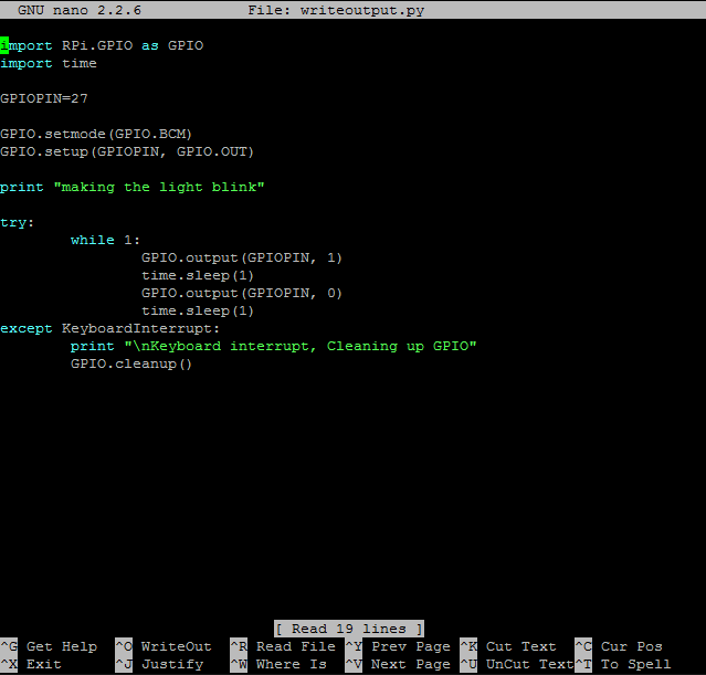
Here is an even simpler breadboard. Grey is going from GPIO27 on the pi to the positive lead on an LED which has the other lead grounded. Again your LED usually needs to somehow be grounded to the pi but in this case I'm using the same 5v power source so it does not. Also use a resistor to limit draw from GPIO to 16mA or less.
Here's an example of some code that will make the LED blink by alternating 3.3v and 0v out each second on GPIO pin 27.


Of course the output in the console is very anti-climactic. I should have put in an echo that said "turning light on" when setting the pin to 1 and "turning light off" when setting the pin to 0. Now your output doesn't necessarily need to go to an LED, it can go to a transistor to drive a relay. I'm still learning about transistors myself but have ordered some releays that will get here in a few days. When they do, I'll write something up on how to drive them via a pi.

The lower Positive/Negative pair are powering the motion sensor.
The brown wire is the signal coming from the motion sensor.
The yellow wire is going to the PI's GPIO4 pin.
The grey/purple wire is coming from the PI's GPIO27 pin to the positive end of a grounded LED.

Here is some code that listens for a signal on GPIO4 and will output one on GPIO27. Notice that I had to pick new names for the pins since there are more than one. Instead of GPIOPIN, I'm using GPIOinput and GPIOoutput. You will need to also update any references from GPIOPIN in your code if applicable. You only need to do GPIO.setmode(GPIO.BCM) one time for any GPIO pins you reference.
You can see how the GPIOinput and GPIOoutput pins are setup on seperate lines, then I toggle the output to 1 for 1 second, then toggle it to 0. I did this for two reasons, first when you set up the the output it seems to start as 1 so you need to disable it, and secondly having the light come on for 1 second helps you know that the script is actually starting properly.
The definitions (functions) should look really familiar from the examples above. The whole thing runs forever in that while 1 loop, where whenever motion is sensed, the pi will keep calling the "ToggleOutput()" function until it stops. The "ToggleOutput()" function blinks the LED and this time actually prints "blink" every time the LED is going to blink. With a .1 second sleep, you should see the light flash about 5 times a second (but only when there is motion.

And there you have it! When the sensor sees motion, it sends the 3.3v signal to the pi. that triggers the pi to tell you that there was motion and start repeatedly calling the ToggleOutput() function that blinks the LED as long as the motion continues. At the end of the runtime there was a longer set of blinks because it was longer continuous motion. Neat!
Having an input signal trigger an output signal
You're then able to use an input signal to trigger an event in python code that will turn on or off your output signal. So lets make it so that when our motion sensor sends the pi a 3.3v signal, it will blink the LED quickly. We'll set up the breadboard as so:

The lower Positive/Negative pair are powering the motion sensor.
The brown wire is the signal coming from the motion sensor.
The yellow wire is going to the PI's GPIO4 pin.
The grey/purple wire is coming from the PI's GPIO27 pin to the positive end of a grounded LED.

Here is some code that listens for a signal on GPIO4 and will output one on GPIO27. Notice that I had to pick new names for the pins since there are more than one. Instead of GPIOPIN, I'm using GPIOinput and GPIOoutput. You will need to also update any references from GPIOPIN in your code if applicable. You only need to do GPIO.setmode(GPIO.BCM) one time for any GPIO pins you reference.
You can see how the GPIOinput and GPIOoutput pins are setup on seperate lines, then I toggle the output to 1 for 1 second, then toggle it to 0. I did this for two reasons, first when you set up the the output it seems to start as 1 so you need to disable it, and secondly having the light come on for 1 second helps you know that the script is actually starting properly.
The definitions (functions) should look really familiar from the examples above. The whole thing runs forever in that while 1 loop, where whenever motion is sensed, the pi will keep calling the "ToggleOutput()" function until it stops. The "ToggleOutput()" function blinks the LED and this time actually prints "blink" every time the LED is going to blink. With a .1 second sleep, you should see the light flash about 5 times a second (but only when there is motion.

And there you have it! When the sensor sees motion, it sends the 3.3v signal to the pi. that triggers the pi to tell you that there was motion and start repeatedly calling the ToggleOutput() function that blinks the LED as long as the motion continues. At the end of the runtime there was a longer set of blinks because it was longer continuous motion. Neat!
Sensing continuity
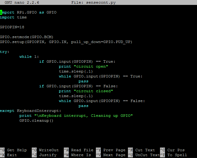
Sensing continuity is fairly straight forward. You basically create a signal on a GPIO pin and sense when it drops (from being grounded). So what I did is use GPIO18 and a GROUND pin to go to a switch. When the circuit is open, the input will show True. When the circuit is closed, the input will show False. The difference in this from sensing an input is that we are using PUD_UP to supply a small voltage to the pin we are listening to which will make the pin show False until it is grounded.
Now just connect wires to GPIO18 and GND. Then connect those wires to a switch, or just strip them and you can touch them together to simulate a switch. The reason for the .1 second sleep is that I saw a little bit of jitter on state changes. That's probably because I was just doing a bad job at making a solid contact.
Here's what you will see as you touch the wires together and pull them apart (or toggle a switch if you are using one). I'm using this to sense my garage door through a magnetic reed switch, and my script will text me with a timestamp whenever the door becomes open or closed. The while/pass portion makes it so that you only have your event happen once time on each state change. I had the option to use a normally open or normally closed switch. Well I used a normally closed switch for my garage door, so if the wiring ever fails it will tell me the door is open and I'll be forced to go check "why my garage door opened at 3am" (sort of a failsafe). If you use a normally open switch, and your wiring fails, it will just never alert you when your door opens.
Well hopefully this helps! It's been a lot of fun learning this and you can imagine all the projects that this opens your pi up to.


Excellent work. Thank you so much!.
ReplyDeleteThank you!!
ReplyDelete